Introduction 5033:2021
AS/NZS 5033:2021 sets out general installation and safety requirements for electrical installations of PV arrays, including d.c. array wiring, electrical protection devices, switching and earthing provisions.
There are a number of changes in requirements in this revision, which include but are not limited to:
(a) change in the scope of this document with respect to maximum PV array power limit
(b) additions of provisions relating to d.c. conditioning units regarding voltage and current calculations
(c) changes to requirements for overcurrent protection and earthing
(d) changes to methods of PV isolation including for d.c conditioning units
(e) changes to requirements for wiring systems and connector requirements
(f) new signs, verification and commissioning requirements.
The new standard also includes the following changes
- The 600V DC limit is being increased up to 1000V DC.
- Rooftop Isolators will be replaced with a requirement for a point of disconnect.
- 35V DC and above is to be deemed hazardous and all conductor parts that can carry 35V or more will have to have earth alarms.
- Cables in ceiling will have to be above 600mm although if the cables have to be within the ceiling and the 600mm they have to be protected by WSX3 rated protection.
- Plan view of the building showing the array, the invert and the points of disconnection and should be part of the documentation provided when the system is installed.
Please note that this standard supersedes AS/NZS 5033:2014 on 19/05/2022.
AS/NZS 5033:2021 Installation and safety requirements for photovoltaic (PV) arrays was in effect in NSW last year and has been in effect from May 2022 for the rest of Australia
5033:2021 new requirement
Labelling / signs for PV cables and enclosures
5.2 Requirements for labels and signs
5.2.1 General
All labels and signs required shall be —
(a) durable and designed to have a lifetime greater than or equal to the service life of the PV system;
(b) constructed of appropriate materials suitable for the location;
(c) fixed in a manner appropriate for the location;
(d) in English;
(e) legible and the letter size to be appropriate for the location(see Note 1);
(f) indelible;
(g) visible where applicable(e.g. some signs may be enclosed in a switchboard cabinet,but visible
when an operator opens the switchboard to perform mainenace or emergency services); and
(h) where installed exposed to direct sunlight conform to Clause 5.2.2.
NOTE 1 Sign lettering should be size with upppercase lettering of 5 mm high and lowercase of 4 mm high per
metre of viewing distance,unless otherwise specialied.
NOTE2 As a guide, the background coour and lettering colour should follow the principles listed below:
(a) Signs for general information should be white with black lettering.
(b) Signs for the essential safety of service personnel should be yellow with black lettering with a
warning symbol.
(c) Signs for attention of emergency personnel should be red with white lettering.
(d) Special signs may use other colours.
5.2.2 UV resistance
Labels/signs exposed to direct sunlight shall be UV resistant.
Labels/signs shall confirm to the following tests as specified in IEC 60068-2-5:2018:
(a) Ten samples of the markings shall be exposed for 720h to open-flame sunshine carbon-arc,in
accordance with ISO 4892-4.
(b) The test samples shall be mounted on the inside of the cylinder in the ultraviolet light
apparatus perpendicular to the light source and in such a way that the samples do not
touch each other.
(c) There shall be continuous exposure to light and intermittent exposure to water spray.The
cycle shall consist of 102 min without water spray and 18 min with water spray.The apparatus
shall operate with an open-flame sunshine carbon-arc lamp,borosilicate glass Type 1,inner
and out optical filters, a spectral irradiance of 0.35W/㎡/nm at 340 nm and a black panel
temperature of (63±3)℃. The temperature of the chamber shall be (45±3)℃.The relative
humidity in the chamber shall be (50±5)%.
Legibility of markings on equipment intended for outdoor use shall not be degraded by UV radiation.
EXCEPTION – This requirement does not apply to markings that are physically engraved,
embossed or etched with durable markings.
5.3 Labelling/signs for PV cables and enclosures
5.3.1 Wiring system identification
5.3.1.1 General
Where the wiring system containning PV d.c. cables is not installed directly behind and adjacent to the PV modules, it shall be –
(a) Identified by distinctive labels marked with the word “SOLAR” on the exterior surface of the wiring system over the length of the enclosure at interval not exceeding 2m; and
(b) visible after mounting;
NOTE 1 Where labels are attached directly to PV d.c cables, tags with the words “SOLAR” may be required to meet the sizing guide.
5.3.1.2 In A Ceiling Space Or Accessible Floor Space
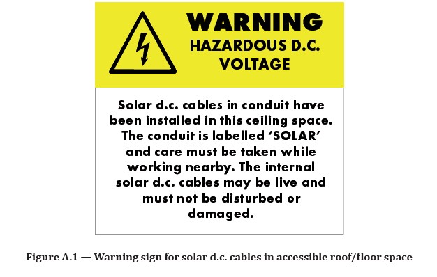
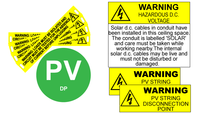
Where PV d.c. wiring systems between the disconnection point and a load break disconnection device are installed in an accessible ceiling space or within an accessible floor space, a warning label shall be installed adjacent to the access point containing the warning symbol and stating the following:
WARNING: HAZAROUS d.c. VOLTAGE
Solar d.c. cables in conduit have been installed in this ceiling space. The conduit is labelled “SOLAR” and care must be taken while working nearby. The internal solar d.c. cables may be live and must not be disturbed or damaged.
NOTE 1 The yellow warning can be separate but added above the information sign so as to simplify sign manufacturing.
The text shall be with a minimum letters size of 10mm.
NOTE2 see Figure A.1.
5.3.2 Signs for junction boxes containing PV d.c. cable terminations
A warning label containing the warning symbol and stating the following shall be attached to the junction
boxes housing the terminations of PV d.c. cable:
NOTE 1 See Figure A.2.
NOTE 2 This does not apply to PV array discounnecting devices as they have their own labelling requirements
(see Clause 5.5.2)
Get the latest standard label with competitive price
5.4 Fire and emergency information
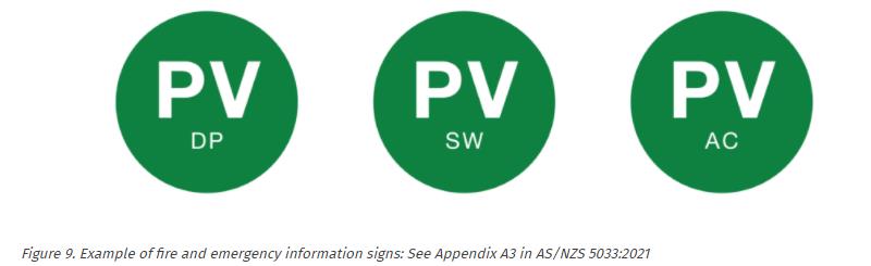
PV systems shall have a circular green reflector sign at least 100 mm diameter with the letters “PV” on or immediately adjacent to the main metering panel and main switchboard, to be readily visible to approaching emergency workers.Below the “PV” lettering shall include the following:
(a) “AC” – For inverters where the calculated PV maximum voltage is less than 120 V d.c. at the inverter PV input; and the PV modules are within 1.5m of the inverter are installed.
(b) “DP” – Where a disconnection point is used as the isolation method.
(c) “SW” – Where a load break disconnection device is used as the isolation method.
Contact with PV solar label supplier
5.5 Labelling/signs for disconnection device
5.5.1 General
Load break disconnection devices shall be marked with an identification name or number consistent
with terminology used in the shutdown procedure.
All switches shall clearly and reliably indicate the isolating position of the device.
NOTE The symbols “O” (off) and “I”(on) are deemed to satisfy this requirement.
5.5.2 PV disconnecting device
5.5.2.1 Load break disconnection device
Load break disconnectors shall be provided with a sign affixed in a prominent location with the
following text:
PV ARRAY d.c. ISOLATOR
Where multiple isolation/disconnection devices are used that are not ganged ( see Clause 4.5.4.2) the
following sign shall be fixed adjacent to the PCE and have a warning label containing a warning symbol
and stating:
WARNING: MULTIPLE d.c. SOURCES
TURN OFF ALL d.c. ISOLATORS TO ISOLATE EQUIPMENT
5.5.2.2 Disconnectioin point
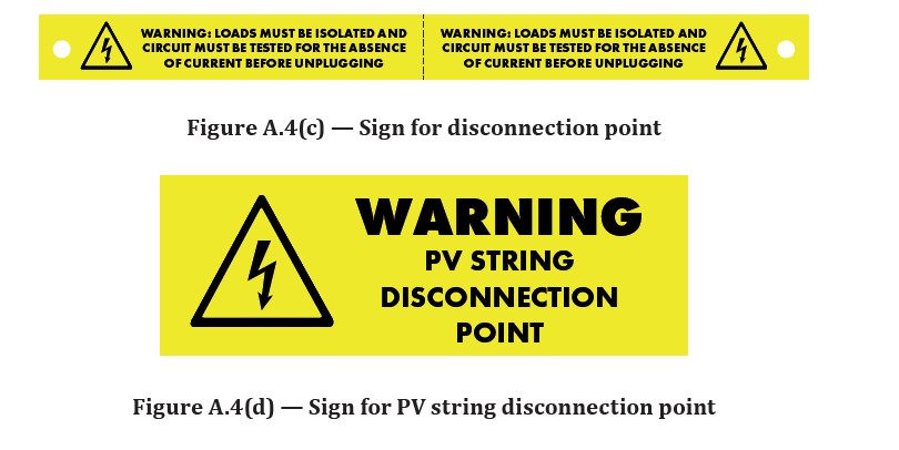
A sign containing the following text shall be attached to both the positive and negative cable within 100mm of the disconnection piont of the PV string:
WARNING: LOADS MUST BE ISOLATED AND CIRCUIT MUST BE TESTED FOR THE ABSENCE OF CURRENT BEFORE UNPLUGGING
NOTE 1 See Figuire A.4(c).
A sign containing the following text shall be attached to the PV module or structure within 300mm of the disconnection piont to identify the location of the disconnetction point:
WARNING: PV STRING DISCONNECTION POINT
NOTE 2 See Figure A.4(d).
The text shall be with a minimum letter size of 10 mm.

Deep dive on the new AS/NZS 5033:2021 Updates
AS/NZS 5033:2021 Update – What You Need to Know ?
Are you finding a good manufacturer who supply New Standard solar label kit / warning sign ?
Download Free PDFGet Solar Label Pricing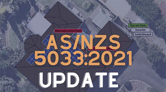
What You Need to Know ?
Send Me The Freebie via Email
History AS/NZS 5033
The draft of amendments to AS/NZS 5033:2014 Installation and safety requirements for photovoltaic (PV) arrays was released for public comment in early February 2018. The comments period will close on 15th March 2018. The draft amendment 1:2018 and draft amendment 2:2018 are available for download free of charge from SAI Global.
Standards updates and amendments are a necessary hurdle for an industry that is constantly growing in size and experience, and that encounters an ever-broadening range of products. Amendments are introduced to standards to better reflect current PV system installation practices and applications.
The main changes which are of interest to PV system installers and designers would be the changes to DC isolators’ applicable utilisation category and sizing requirement, and installation methods pertaining to wiring systems in junction boxes, combiner boxes and isolator/disconnector boxes. Additional requirements on hardware such as inverters and isolator enclosures have also been introduced, which can affect selection of equipment for PV systems.
To assist the industry with understanding and providing feedback on the draft amendments, this article is produced to describe the key updates to the standard and what they mean for PV system designers and installers. Please note that not all changes are included here; GSES recommends that installers read the standard for themselves to ensure they are aware of all draft changes and have an opportunity to provide comments prior to publication.
Relative Links
Latest Guidance of AS/NZS 5033:2021
video guidance
About AS/NZS 5033 ( 2012 ~ 2021 )
The AS/NZ 5033 is the Australian Standards for the installation of solar panels.
Changes to Australian solar PV installation standard AS5033: What’s new?
AS/NZS 5033 – Changes
AS/NZS 4777.1 2022 – Key updates to the standard and what they mean for installers
Posted on March 16, 2017 by GSES