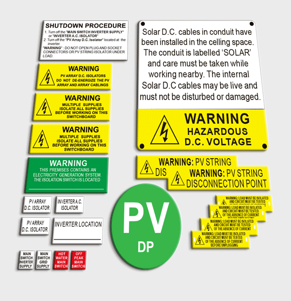
AS/NZS 5033:2021 NEW REQUIREMENT Labelling / signs for PV cables and enclosures
5.2 Requirements For Labels And Signs
5.2.1 General
All labels and signs required shall be —
(a) durable and designed to have a lifetime greater than or equal to the service life of the PV system;
(b) constructed of appropriate materials suitable for the location;
(c) fixed in a manner appropriate for the location;
(d) in English;
(e) legible and the letter size to be appropriate for the location(see Note 1);
(f) indelible;
(g) visible where applicable(e.g. some signs may be enclosed in a switchboard cabinet,but visible
when an operator opens the switchboard to perform mainenace or emergency services); and
(h) where installed exposed to direct sunlight conform to Clause 5.2.2.
NOTE 1 Sign lettering should be size with upppercase lettering of 5 mm high and lowercase of 4 mm high per metre of viewing distance,unless otherwise specialied.
NOTE2 As a guide, the background coour and lettering colour should follow the principles listed below:
(a) Signs for general information should be white with black lettering.
(b) Signs for the essential safety of service personnel should be yellow with black lettering with a
warning symbol.
(c) Signs for attention of emergency personnel should be red with white lettering.
(d) Special signs may use other colours.
5.2.2 UV Resistance
Labels/signs exposed to direct sunlight shall be UV resistant.
Labels/signs shall confirm to the following tests as specified in IEC 60068-2-5:2018:
(a) Ten samples of the markings shall be exposed for 720h to open-flame sunshine carbon-arc,in
accordance with ISO 4892-4.
(b) The test samples shall be mounted on the inside of the cylinder in the ultraviolet light
apparatus perpendicular to the light source and in such a way that the samples do not
touch each other.
(c) There shall be continuous exposure to light and intermittent exposure to water spray.The
cycle shall consist of 102 min without water spray and 18 min with water spray.The apparatus
shall operate with an open-flame sunshine carbon-arc lamp,borosilicate glass Type 1,inner
and out optical filters, a spectral irradiance of 0.35W/㎡/nm at 340 nm and a black panel
temperature of (63±3)℃. The temperature of the chamber shall be (45±3)℃.The relative
humidity in the chamber shall be (50±5)%.
Legibility of markings on equipment intended for outdoor use shall not be degraded by UV radiation.
EXCEPTION – This requirement does not apply to markings that are physically engraved,
embossed or etched with durable markings.
5.3 Labelling/Signs For PV Cables And Enclosures
5.3.1 Wiring system identification
5.3.1.1 General
Where the wiring system containning PV d.c. cables is not installed directly behind and adjacent to the PV modules, it shall be –
(a) Identified by distinctive labels marked with the word “SOLAR” on the exterior surface of the wiring system over the length of the enclosure at interval not exceeding 2m; and
(b) visible after mounting;
NOTE 1 Where labels are attached directly to PV d.c cables, tags with the words “SOLAR” may be required to meet the sizing guide.
NOTE 2 The backgroud colour and lettering colour on the exterior surface of wiring system should have
appropriate contrast so that it is clearly visible and readable.Any colours that meet the requirement of this
clause may be used.
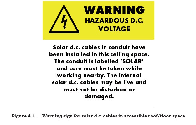
5.3.1.2 In A Ceiling Space Or Accessible Floor Space
Where PV d.c. wiring systems between the disconnection point and a load break disconnection device are installed in an accessible ceiling space or within an accessible floor space, a warning label shall be installed adjacent to the access point containing the warning symbol and stating the following:
WARNING: HAZAROUS d.c. VOLTAGE
Solar d.c. cables in conduit have been installed in this ceiling space. The conduit is labelled “SOLAR” and care must be taken while working nearby. The internal solar d.c. cables may be live and must not be disturbed or damaged.
NOTE 1 The yellow warning can be separate but added above the information sign so as to simplify sign manufacturing.
The text shall be with a minimum letters size of 10mm.
NOTE2 see Figure A.1.
5.3.2 Signs For Junction Boxes Containing PV D.C. Cable Terminations
A warning label containing the warning symbol and stating the following shall be attached to the junction
boxes housing the terminations of PV d.c. cable:
NOTE 1 See Figure A.2.
NOTE 2 This does not apply to PV array discounnecting devices as they have their own labelling requirements(see Clause 5.5.2)
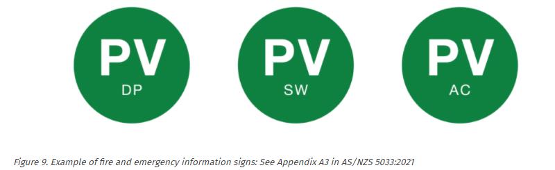
5.4 Fire And Emergency Information
PV systems shall have a circular green reflector sign at least 100 mm diameter with the letters “PV” on or immediately adjacent to the main metering panel and main switchboard, to be readily visible to approaching emergency workers.Below the “PV” lettering shall include the following:
(a) “AC” – For inverters where the calculated PV maximum voltage is less than 120 V d.c. at the inverter PV input; and the PV modules are within 1.5m of the inverter are installed.
(b) “DP” – Where a disconnection point is used as the isolation method.
(c) “SW” – Where a load break disconnection device is used as the isolation method.
5.5 Labelling/Signs For Disconnection Device
5.5.1 General
Load break disconnection devices shall be marked with an identification name or number consistent
with terminology used in the shutdown procedure.
All switches shall clearly and reliably indicate the isolating position of the device.
NOTE The symbols “O” (off) and “I”(on) are deemed to satisfy this requirement.
5.5.2 PV Disconnecting Device
5.5.2.1 Load Break Disconnection Device
Load break disconnectors shall be provided with a sign affixed in a prominent location with the following text:
PV ARRAY d.c. ISOLATOR
Where multiple isolation/disconnection devices are used that are not ganged ( see Clause 4.5.4.2) the following sign shall be fixed adjacent to the PCE and have a warning label containing a warning symbol and stating:
WARNING: MULTIPLE d.c. SOURCES
TURN OFF ALL d.c. ISOLATORS TO ISOLATE EQUIPMENT
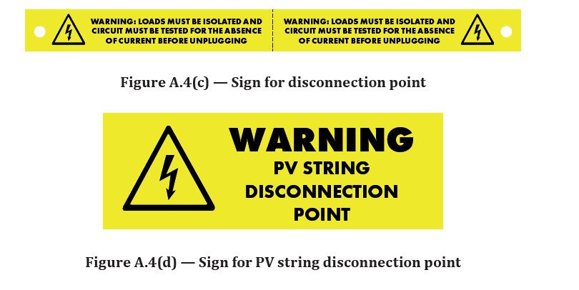
5.5.2.2 Disconnectioin Point
A sign containing the following text shall be attached to both the positive and negative cable within 100mm of the disconnection piont of the PV string:
WARNING: LOADS MUST BE ISOLATED AND CIRCUIT MUST BE TESTED FOR THE ABSENCE OF CURRENT BEFORE UNPLUGGING
NOTE 1 See Figuire A.4(c).
A sign containing the following text shall be attached to the PV module or structure within 300mm of the disconnection piont to identify the location of the disconnetction point:
WARNING: PV STRING DISCONNECTION POINT
NOTE 2 See Figure A.4(d).
The text shall be with a minimum letter size of 10 mm.
What is the latest labeling requirements in 2026?
SAA Labelling Support Grid connected Systems 2026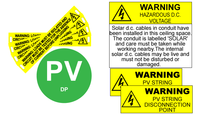
How much new labels cost?
Need solar label kit compliance to the latest standard AS5033:2021 ?